Old Model Boats...
Where do old model boat kits go when they die?
The design
Looking at the old actuator designs, they frequently required complex metal bending work and items like Mighty Midget motors - all unavailable today. So the design needed to make use of readily available modern items. It needed to be easy to make - skilled craftsmanship is a bit lacking today - certainly in my workshop! And ideally it would perform the full range of single-channel services, including 'quick-blip'.
What came out of the skunkworks was a classic circular cam, halted by microswitches, and with an arm driven by a pin and slot to provide a push-pull output. I was thinking of something akin to the Graupner 'Kinematic'. Since this design uses microswitches perhaps we could call it a Micromatic...? There is no complex shaping, and the output is surprisingly powerful and reliable. The only disadvantage I have found is that there is no positive lock for the centre position, so that needs to be adjusted carefully - but it centers adequately for me. The cost is less than �5. So welcome to the very latest in 1960s technology!
Description of the action.
If you read this in conjunction with the image on the right the design should make sense!
The actuator comprises a rotating disk powered by a geared motor of about 120RPM. The disk holds a pin which drives a slotted arm in a push-pull cycle. The disk has a dip in the circumference and three microswitches arranged around it - each of which are operated when their arms engage with the dip. These are the 'centre' microswitch, and the 'left' and 'right' microswitches.
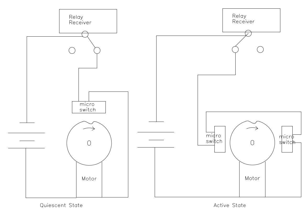
The actuator is driven by the output from a single-channel relay receiver. This provides power on one line when the receiver is quiescent, and power on another when it it is activated.
The 'quiescent power' line drives the actuator motor through the centre microswitch, so whenever the receiver is not activated the actuator will rotate until the disk dip is next to the centre micoswitch and it is thrown. At that point the actuator is centred, and it halts.
The 'activated power' line drives the actuator motor through the 'side' (left and right) microswitchs, so whenever the receiver is activated the actuator will rotate until the disk dip is next to the first side micoswitch and it is thrown. At that point the actuator halts. If the transmiter button is then released and the receiever goes quiescent the actuator then continues to move around driven by power through the centre microswitch. If the transmitter were then to be keyed again rapidly (giving a 'push-release-push cycle) the actuator would halt at the next side microswitch.
This gives us a 'compound' actuator, where 'Push.....Release' always gives a right turn, while 'Push..Release..Push.....' gives a left turn.
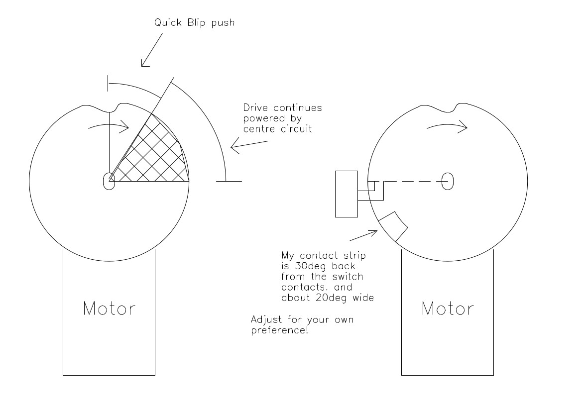
A 'Quick-Blip' is defined as the actuator entering its 'quiescent' (centering) state BEFORE the first side microswitch has engaged. This means that power is flowing through the centre microswitch during the first quarter turn of the actuator disk.Usually, if a turn is being requested, power would be flowing through the side microswitches at this point. The hatched area opposite shows the 'quick-blip' detection area.
It is therefore easy to place a small switch on that first quadrant and connect it to the centering microswitch. If that switch is actioned at the same time as power from the centre is applied, a quick pulse of energy will be output. This can be used by another actuator to perform motor switching...
In practice, it is more convenient to place the contact strip elsewhere on the disk, so long as the connection occurs during the first 90 degrees of turn. The first few degrees must be avoided since this is when the button is pressed to start the action. I have found that a position between 30 deg and 50 degrees after the start matches my button-pressing well.
The QB switch is made from a bit of brass wire and thin brass sheet. Bend the wires as shown and attach the brass sheet to the disk with two small saw cuts, as shown in the picture.You will find that three small strips of 1/8" acrylic will hold the brass contacts at just the right height - twist them a bit before fixing to ensure a downward spring force.
Dodgy Geezer me fabricavit. Technical hat-tips - Thank you for the free
textures,
domain names, and
HTML editor....
We hope that some of them will come here...
Since this actuator depends on microswitch activation to halt rotation at the correct position, it is important that this be done rapidly. There is a lot of rotational energy in the motor which needs to be damped, otherwise excessive overshoot will occur. This is done in two ways. The motor is dynamically braked by connecting a low-value resistor across its terminals, and a friction brake is applied to the circumference.
The rather complex wiring enables the microswitches to provide power to the motor and short it through the resistor whenever it is to be halted. An 20ohm resistor seems to work quite well...
The friction brake is applied at all times, and needs to be adjusted to take account of the particular motor/voltage being used. It is important for smooth running that the disk is accurately centred, otherwise slight wobble will make the brake bind in some positions. Luckily, it is easy to place a bit of fine sandpaper on the brake surface and rotate the disk until any high points are leveled.
The microswitches can, of course, be adjusted sideways slightly to take account of the inevitable slight overrun. The centre position is most important, and should be able to be reproduced precisely with left, right and quick-blip signals. You will find that the brake is quite sensitive, and even a slight turn will have an effect on the halting position.