Old Model Boats...
Where do old model boat kits go when they die?
Wiring up the actuator is a bit complex!
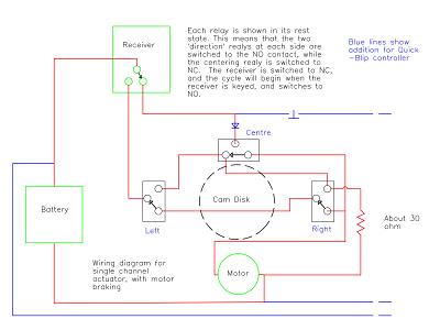
There are two seperate circuits - the centering one and the left-right one. There is also the motor shorting circuit for dynamic braking, and the output for the Quick-Blip. No PCM or S-Bus in those days!
It is part of the fun (?) of getting an old S/C system to work - and a major reason for their unreliability. Just one connection coming adrift in a high-vibration environment will lose control.. Make sure all your connections are tight!
For this reason I included a bit of Veroboard to terminate all the connections. It makes the wiring more controllable and tidier.
Actuator wiring.
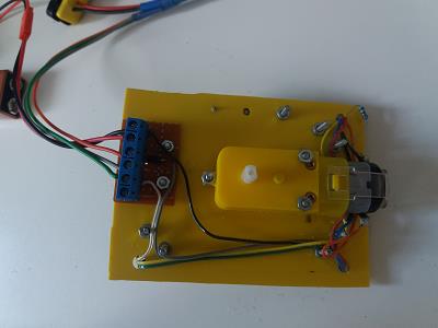
Here is a shot of the prototype wiring - all underneath the board. As its upside down, the terminal board is next to the Right microswitch, and then the cabling passes up to the Centre microswitch, the motor, and finally the Left microswitch at the top right of the picture..
A word about definitions.I look at the actuator from above, with the arm pivot and brake at the bottom of the picture. Looked at this way, the Centre microswitch is top right, below that is the Right microswitch, and over to the left is the Left microswitch.
Each microswitch has three contacts:
Common - Com.
Normally Open - NO.
Normally closed - NC.
So the letters RNO stand for the Normally Open contact on the Right microswitch.
Dodgy Geezer me fabricavit. Technical hat-tips - Thank you for the free
textures,
domain names, and
HTML editor....
We hope that some of them will come here...
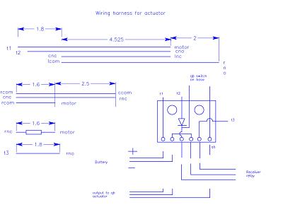
Using the above notation, this diagram may help you to create a decent harness out of ribbon cable. Cut the wires to these lengths and you should be able to wire the actuator up with the minimum of fuss. I have added my terminal block wiring.
The Quick-Blip switch wiring is, of course, optional. The diode on the terminal block is only needed if you want to add this feature. Note that only three harness wires terminate on the terminal block - t1, 2 1 and 3.


