Old Model Boats...
Where do old model boat kits go when they die?
Print the base cutting lines and stick to a piece of 1/8" acrylic. It provides all the hole positions to drill - if you are using the recommended parts.
It's worth checking the hole dimensions before cutting the holes - I have found some Chinese motors which look similar to have the holes in slightly different positions!
Assembling the Hardware!
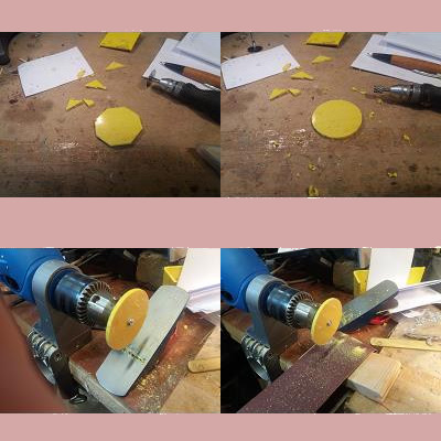
Here are some stages in making a smooth disk...
1 - cut a rough hexagon with a saw
2 - round it off with a Dremel cutter
3 - run it over a plane to rapidly remove high points
4 - finish off with sandpaper...
Dodgy Geezer me fabricavit. Technical hat-tips - Thank you for the free
textures,
domain names, and
HTML editor....
We hope that some of them will come here...
The Brass Arm Mount and Brake are simply cut from sheet with tinsnips
Here a block of wood has been drilled to hold the arm pivot at 90deg.
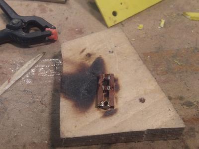
Note that the arm pivot stands proud of the underneath of the mount. This gives the solder added strength. A hole is drilled in the base to accomodate it when it is assembled.
Here is the pivot pin soldered to the base, and the brake blade with a short tube soldered as a mount.
The actuator arm and the disk pin arm are soldered similarly, using the wood block 90deg jig.
Here you can see a partly assembled base/motor/arm mount in the background, with a new soldered arm to the left. The disk pin arm is being arranged in preparation for soldering.
Soldering complete!
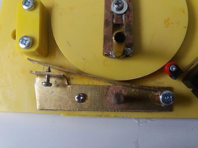
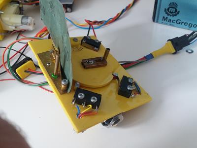
And here is a shot of the arm mount, brake and disk pin arm all assembled.
You can also see one of the microswitches, and I have added the 'Quick-Blip' switch mount. This last is not needed, of course, if you are only making a rudder actuator.
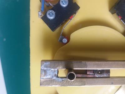
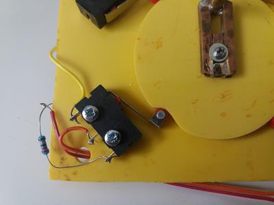
When the arms and centre microswitch are connected. nudge the disk around with short blips of voltage until the arm is dead centre. You can see the bolt holding the disk on throught the central gap in the arm.
At that point mark the disk where the centre microswitch roller is. That will be where you need to cut the dip in the side of the disk. The picture shows the end configuration.
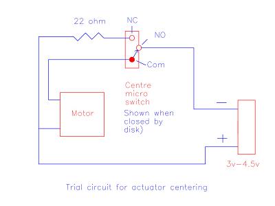
At this point you can wire up the centre microswitch and power up the actuator. If you raise the arm of the centre micoswitch the disk should perform one revolution and return to the centre position.
If it overruns, lower the voltage you are using or increase pressure on the brake. If
Here is the circuit you will need to wire up the centre switch. This is just a temporary connection to adjust the actuator so that it operates reliably, using the tests above.
Once this is achieved, we can wire up the complete circuit. The data for this is on the next page...
Run the disk around several times. Adjust the brake to give a reliable stop in the centre
If the brake seems variable and sticky, this is probably because the disk is slightly off-centre. This is easily fixed by putting a sheet of fine sandpaper along the brake and running the disk until there is no wobble and the circumference is perfectly smooth...
